Mold Construction
For high volume production, the initial expense of quality tooling is a sound investment. The choice of tool steel will depend on the quantity and quality of parts to be produced and will be primarily determined by the type of rigid substrate being used in the application. If a reinforced substrate material is used a high hardness abrasion resistant steel may be required.
Most GLS materials overmolding materials are generally non-abrasive / non-corrosive and replicate the mold surface fairly well.
- A polished mold is required to produce a glossy or good clarity surface.
- To produce a part with a matted appearance of a thermoset rubber, a rougher mold surface is required. In general, the rough surface produced when EDM the cavity will produce a good surface and good release from the mold.
- Vapor honing, sand or bead blasting and chemical etching may also be used to produce surfaces with varying degrees of gloss and appearance.
- To aid in release, the cavity or core may be coated with a release coating such as PTFE impregnated nickel after it has been given a sand blast or EDM finish.
Tool Layout
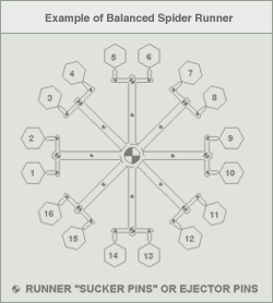
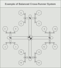
Multi-cavity tool layouts should be balanced. In a balanced runner system, molten material flows into each cavity at equal times and pressure. Examples of balanced spider and cross-runner systems are shown in the figures below:


Runner Configuration and Design
For conventional cold runner tools, full-round runners are best because they provide the lease resistance to flow and minimize cooling in the runner. Cooling is minimized because full round runners have less surface area and therefore keep the material molten longer.
The second most efficient runner cross-section is the modified trapezoid. This type of geometry most closely simulates a full round runner but only requires machining in only one plate.
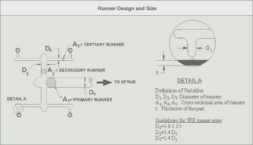
Runner dimensions rarely exceed 0.300" even for the main runner. Cold slug wells should be used each time the runner makes a turn or divides.
The figure below illustrates typical runner dimensions:

Hot Runner Systems
Hot runner tool layout should be naturally or geometrically balanced. Externally heated manifolds are best. Internally heated systems, which use torpedo heaters, are not recommended because they have hot spots, stagnation zones and partially solidified material clinging to the walls.
All passages should have highly polished circular cross sections with gentle bends to minimize the possibility of stagnation zones, and a diameter of 0.250" to 0.375". Individualized zone controls will allow for some balance adjustment and will improve part quality.
Gate Design
All conventional gating types are suitable for processing GLS elastomers. The type of gate and the location, relative to the part, can affect the following:
- Part packing
- Gate removal or vestige
- Part cosmetic appearance
- Part dimensions including substrate warpage.
The type of gating is dependent on both part and tool design. For automatically degating tools, the highly elastic nature of softer TPEs makes gate design such as submarine gates or three plate tools with self-degating drops more difficult. Higher hardness and filled grades usually have lower ultimate elongation and therefore are more easily degated. To assure that a gate will break at a specific location, the land length should be short to create a high stress concentration.
The table below summarizes the advantages and disadvantages of a variety of gate designs. For more in-depth information about a specific gate design, please download the full-length Overmolding Guide.
Comparison of Gate Types
|
Gate Type
|
Advantage
|
Disadvantage
|
|
Edge/Tab/Pin Gate
|
- Appropriate for flat parts
- Easy to machine and modify
|
- Post-mold gate/runner removal
- Larger gate vestige
|
|
Submarine Gate
|
- Automatic gate removal
- Minimal gate vestige
|
- More difficult to machine
- More difficult to extract
|
|
Back gating through a pin and hole in substrate
|
- No gate vestige on front side of part
|
- More complex
- Post mold trimming
- Potential surface sink
|
|
Diaphragm gate
|
- Concentricity
- Appropriate for round parts
- No knit lines
|
- Post molding gate and runner removal
- Scrap
|
|
Pin gate (3-plate)
|
- Automatic gate removal
- Minimal gate vestige
- Localized cooling
|
- Requires floater plate
- More scrap
- Higher tool cost
|
|
Valve gate (hot runner systems)
|
- Minimal gate vestige
- Positive shut-off
- Minimizes post pack
|
- High tool cost
- Higher maintenance
|


